Lab 7 - ECE 421L
Finish Tutorial 5
Schematic:
Symbol:
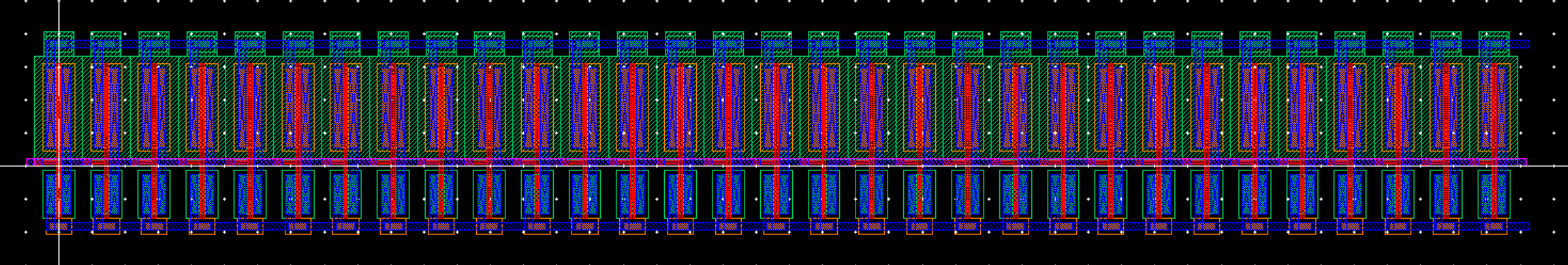
Layout:
DRC:
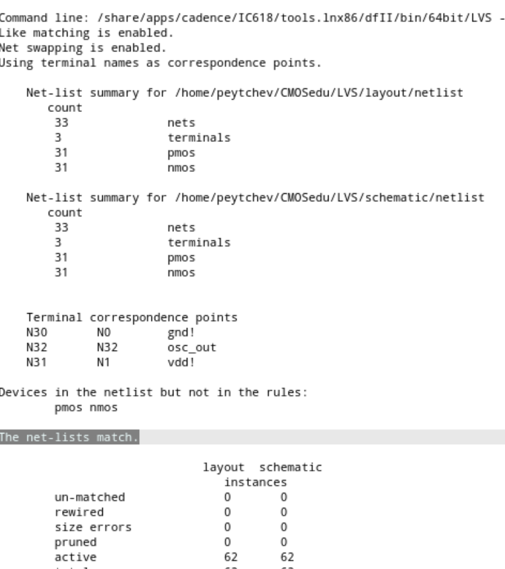
LVS:
Lab 7
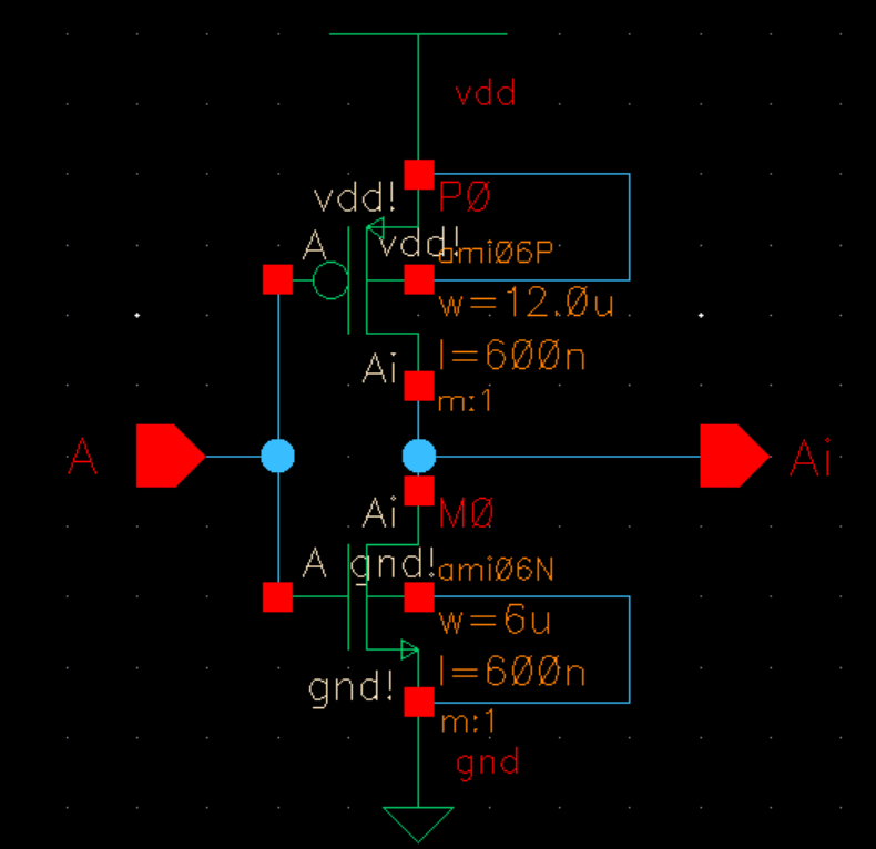
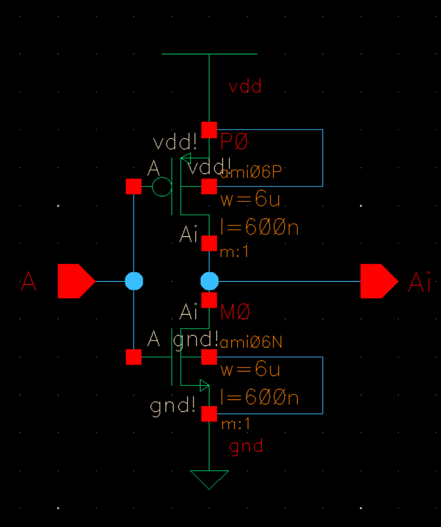
Inverter:
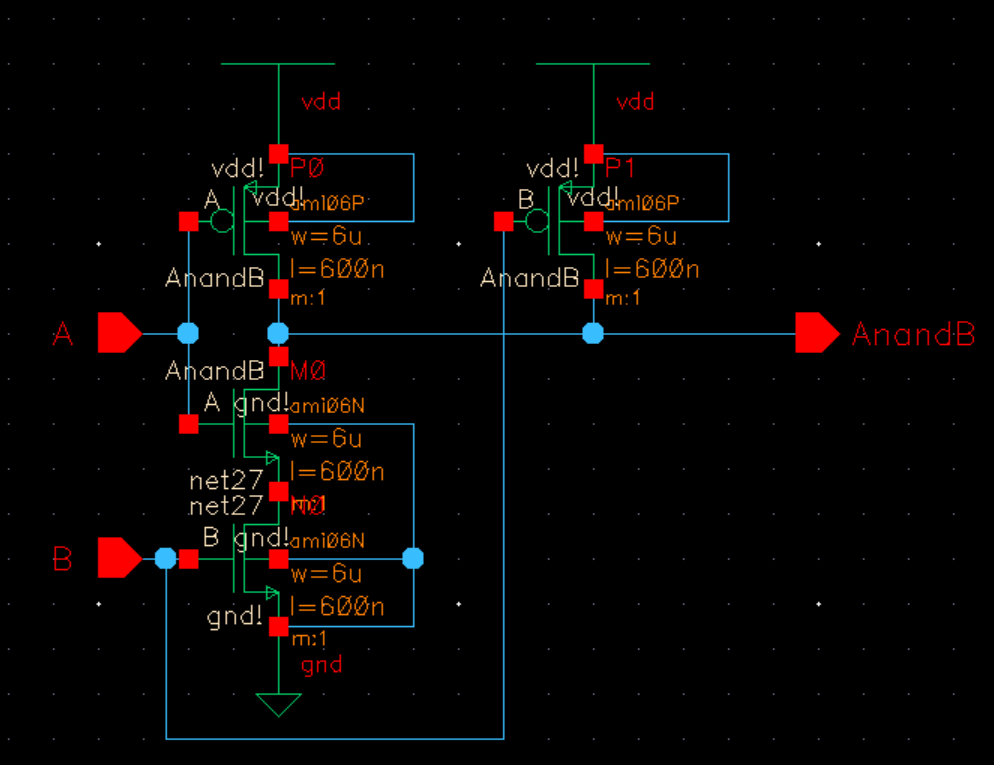
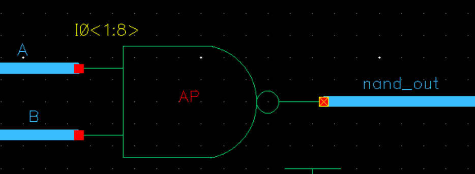
NAND
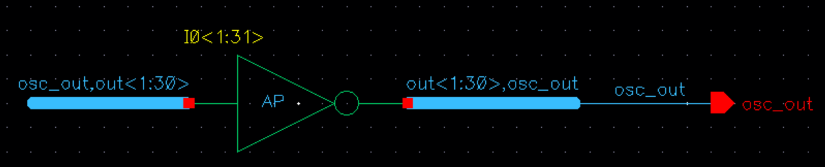
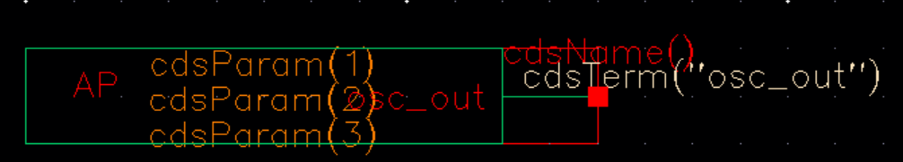
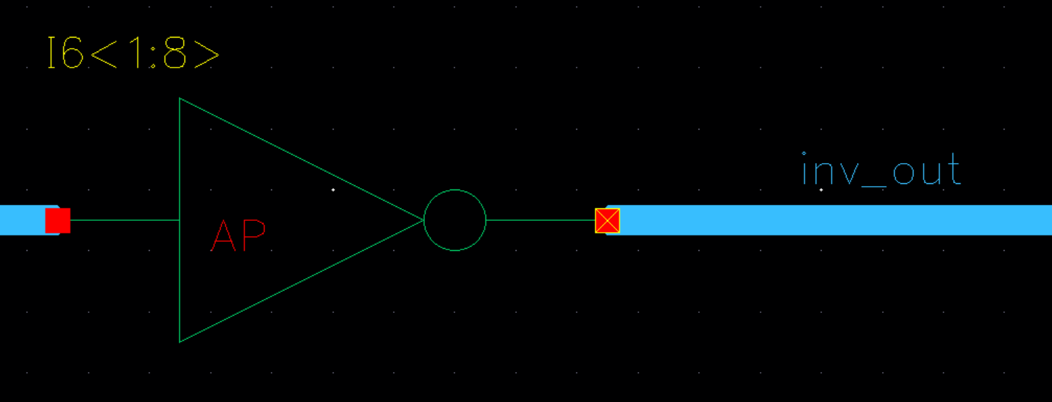
Symbol:
AND
We combined a NAND gate with an Invertor to get this AND gate.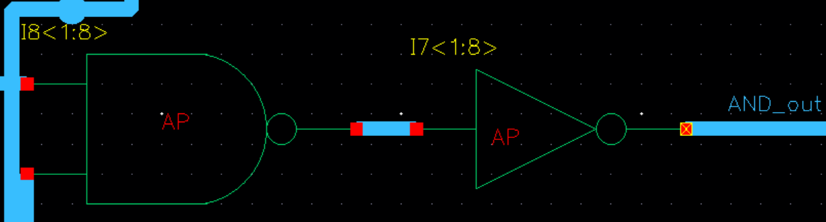
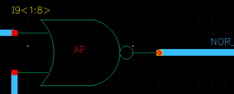
NOR
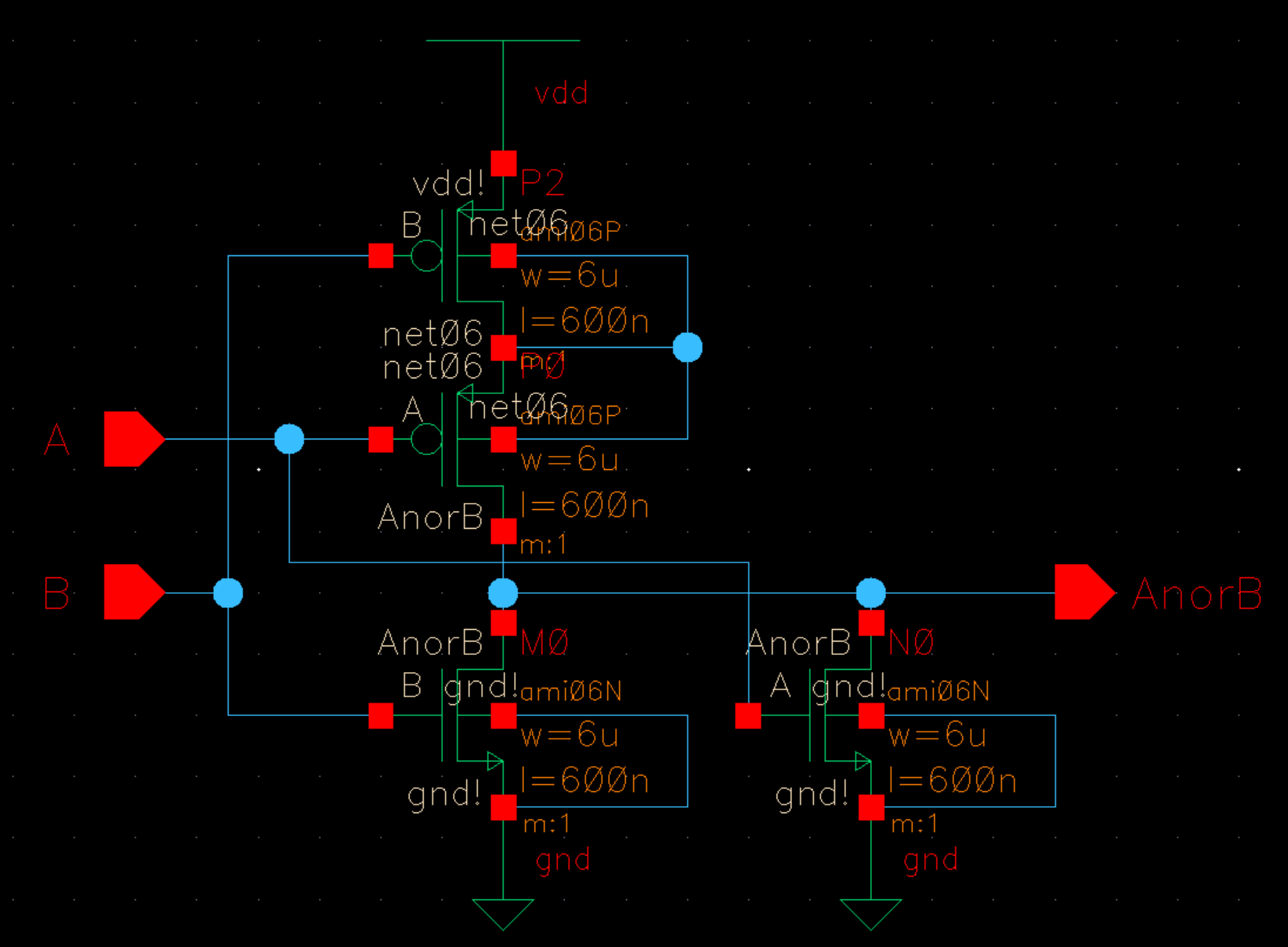
Symbol:
OR
We combined a NOR with an inverter to get an OR so their respective schematics will be above.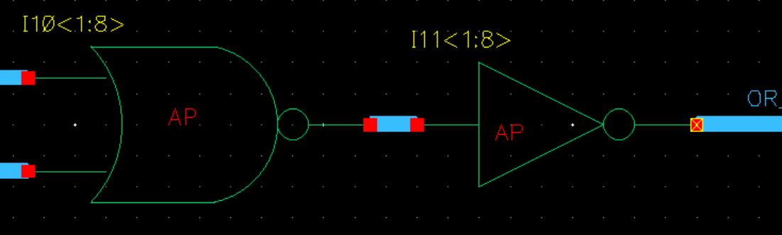
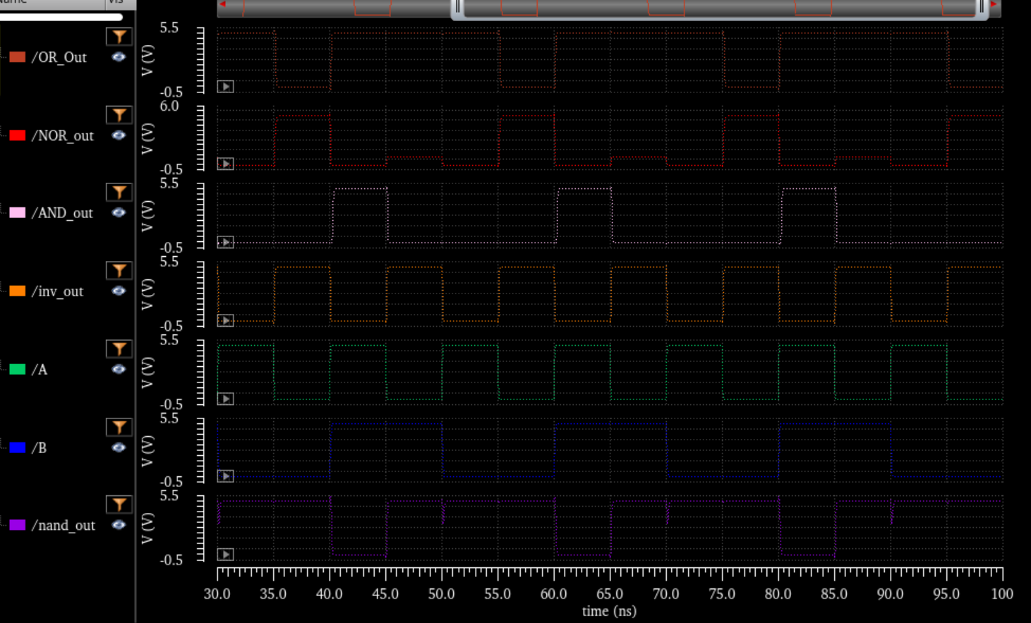
Simulation:
Simulation of inverter, nand, and, or and nor:
(Inverter linked to input A)
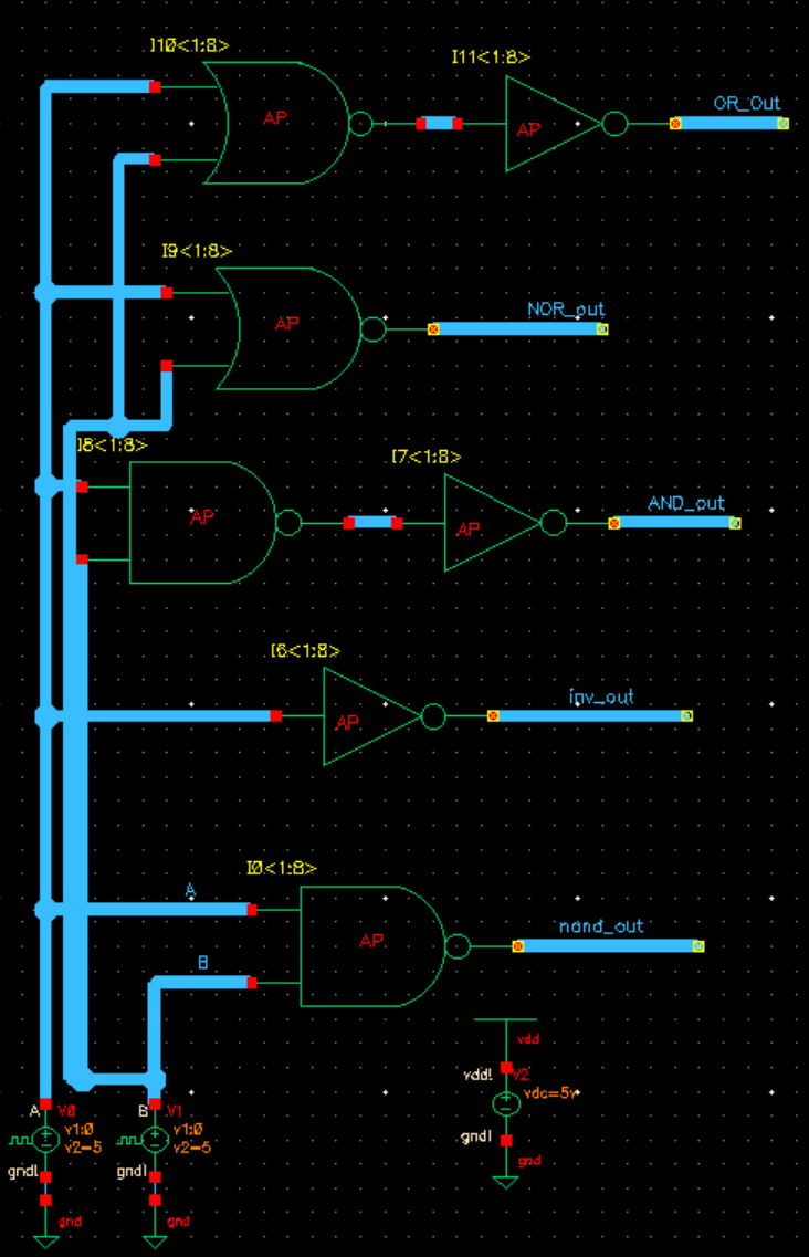
Sim Schematic for the above.
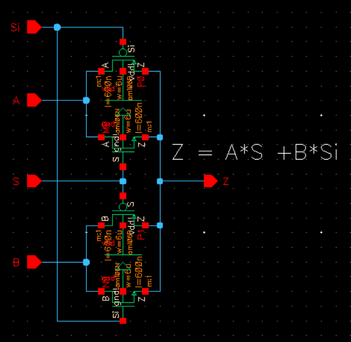
2-1 MUX:
Schematic:
Symbol:
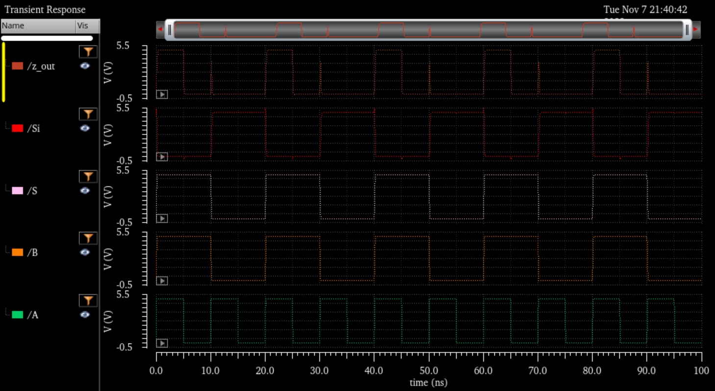
SIM:
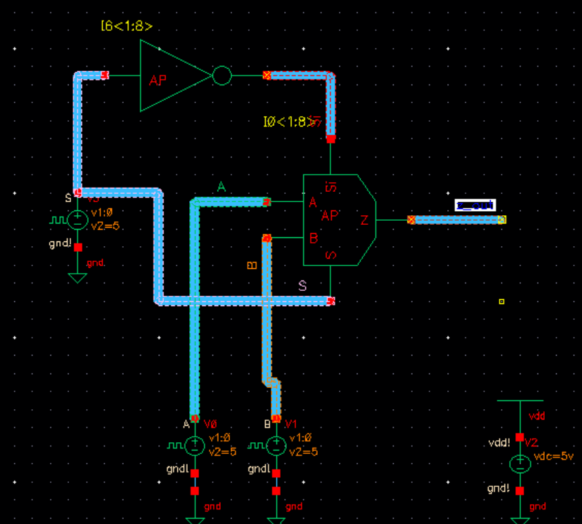
Sim Circuit:
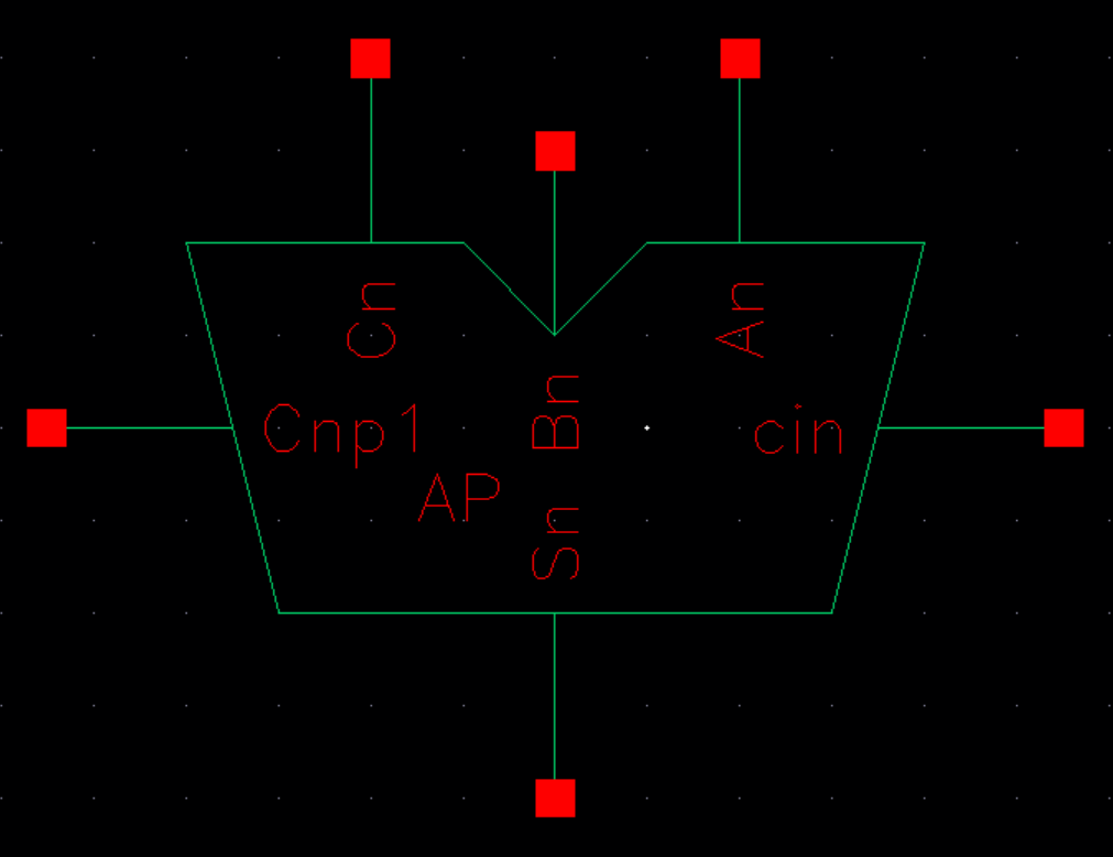
Full Adder:
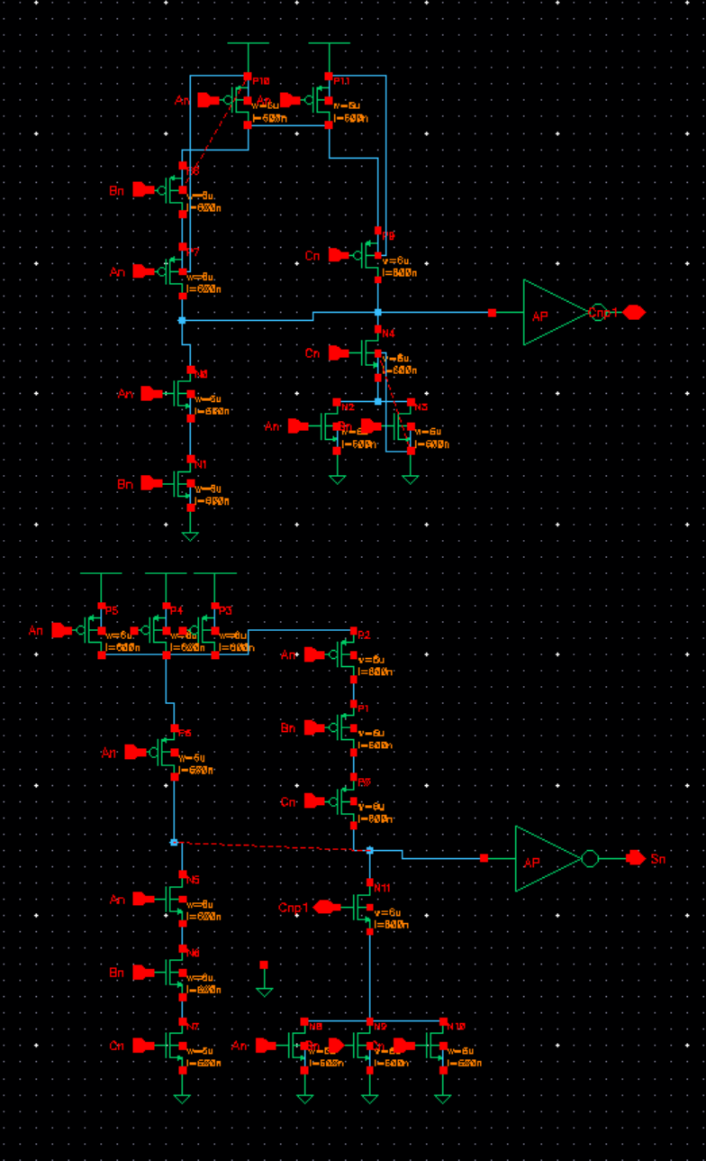
Schematic:
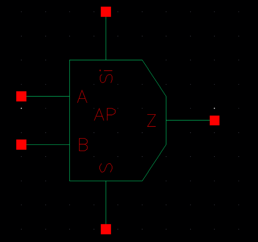
Symbol:
Backup:
Backed up everything to zip file